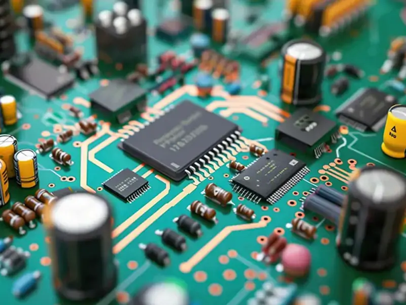
When observing the motherboard of any electronic device, such as a smartphone, computer, or industrial controller, you will always see various types of "interfaces" or "slots." These are PCB connectors. Simply put, PCB connectors are components soldered onto a printed circuit board (PCB) to establish reliable and detachable electrical and mechanical connections. Furthermore, as electronic products evolve towards higher density, higher speed, and miniaturization, circuit structures are becoming increasingly complex. In this context, PCB connectors play a crucial role in complex circuits, directly impacting the reliability of PCB assembly (PCBA) and system performance.
Introduction: Why PCB Connectors Matter in Complex Circuits
The following will be demonstrated across four core dimensions: electrical, mechanical, thermal management, and production and maintenance.
I. Electrical Performance Assurance: Key Nodes for Signal and Power Integrity
1. High-Speed Signal Transmission Bottlenecks
- Impedance Continuity Control: High-quality connectors maintain transmission line impedance matching (typical values 50Ω/100Ω differential), reducing signal reflection.
- Crosstalk Suppression: Optimized layout and shielding design through grounding pins reduce crosstalk to acceptable levels (typically <-40dB).
- Insertion Loss Management: High-frequency connectors utilize low-loss dielectric materials to ensure GHz-level signal attenuation remains within specifications
2. Power Distribution Network Core
- Low Contact Resistance Design: Power pins utilize multi-point contact or large cross-sectional area designs, resulting in contact resistance as low as milliohms.
- Current Carrying Capacity: Appropriate specifications are selected based on load requirements, ranging from milliampere-level signal transmission to hundreds of amperes of power distribution.
- Decoupling Capacitor Integration: Some high-performance connectors integrate decoupling capacitors to optimize power integrity.
II. Mechanical Structure Support: The Foundation of 3D Integration and Reliable Connection
1. High-Density Interconnection SolutionsKey Considerations for Professional Selection
When selecting PCB connectors, engineers should systematically evaluate the following parameters:
- Micro-pitch technology: Modern board-to-board connector pitches have evolved to 0.35mm or even 0.2mm, adapting to high-density layouts.
- Stacking height control: Provides multiple stacking height options (0.5mm-10mm) to meet different space constraints.
- Foolproof design: Mechanical keying prevents incorrect module assembly.
2. Environmental Adaptability Design
- Vibration reliability: Industrial-grade connectors pass the IEC 60068-2-6 vibration test standard.
- Durability indicators: Commercial-grade connectors typically have a mating cycle life of 50-200 times, while industrial-grade connectors can reach 500-1000 times.
- Environmental sealing: IP67/IP68 rated connectors meet the requirements for harsh environment applications.
III. Thermal Management Integration: Key Pathways for Power Device Heat Dissipation
1. Thermal Conduction Optimization
- Thermal Resistance Control: Some connectors are specifically designed as system heat dissipation paths, with thermal resistance as low as 1-5°C/W.
- Power Module Interconnection: High-current connectors integrate heatsink mounting interfaces, supporting active/passive cooling solutions.
2. Thermal Expansion Matching
- CTE Compensation Design: Connector materials match the thermal expansion coefficient of the PCB substrate, avoiding stress failure during temperature cycling.
- Floating Contact Technology: Allows a certain degree of relative displacement to compensate for differences in thermal deformation.
IV. System-Level Value: Manufacturability and Total Life Cycle Cost Optimization
1. Modular Design Advantages
- Functional Partitioning and Isolation: Analog/digital/RF/power circuits are designed on separate boards and interconnected via connectors, reducing design complexity.
- Accelerated Parallel Development: Each module can be independently developed and tested, shortening time to market.
- Flexible Technology Iteration: Core modules can be upgraded independently, extending the platform's life cycle.
2. Production and Maintenance Benefits
- Test Access Points: Provides production test interfaces, simplifying ATE system access.
- On-Site Maintenance Feasibility: Supports board-level repair, reducing mean time to repair (MTTR) by 60-80%.
- Inventory Cost Optimization: Universal connector interfaces promote module standardization, reducing the variety of spare parts.
Key Considerations for Professional Selection
When selecting PCB connectors, engineers should systematically evaluate the following parameters:
| Evaluation Dimension |
Key Parameters |
Typical Impact |
| Electrical Performance |
Current Rating, Contact Resistance, Impedance, Bandwidth |
Determines system power capacity and maximum signal rate |
| Mechanical Characteristics |
Mating Force, Retention Force, Durability, Pitch |
Affects assembly process reliability and density |
| Environmental Specifications |
Operating Temperature, Protection Rating, Corrosion Resistance |
Determines application scenario suitability |
| Reliability |
Vibration/Shock Tolerance, Temperature Cycling Lifetime |
Impacts product warranty period and failure rate |
| Cost Factors |
Unit Price, Assembly Cost, Testing Cost |
Affects Total Cost of Ownership (TCO) |
What Is a PCB Connector in PCB Assembly and Complex Circuit Design?
Definition of a PCB Connector
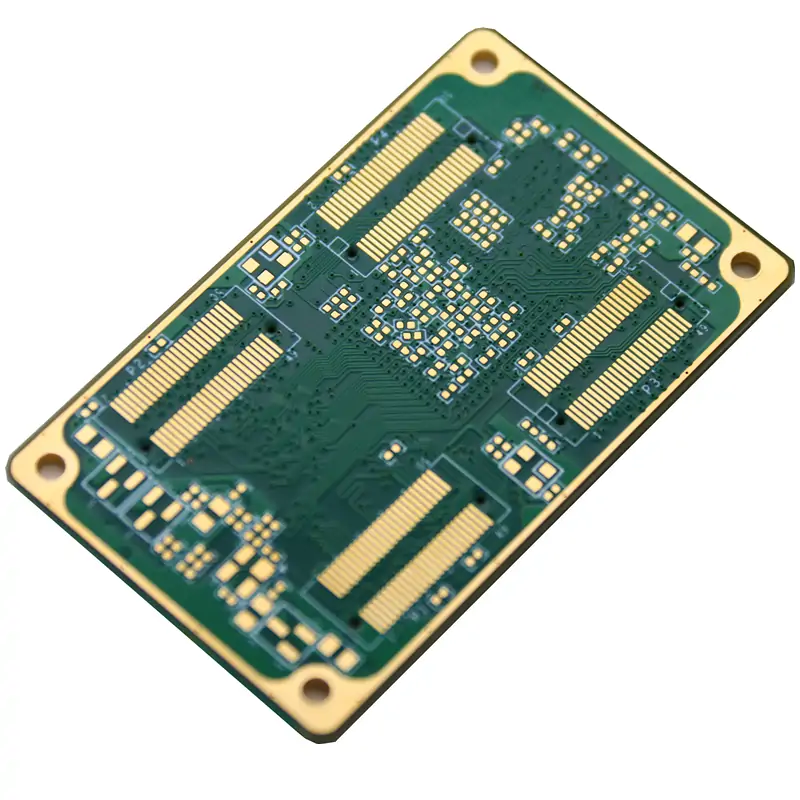
A PCB connector is an electromechanical component used to connect circuits on a printed circuit board to other boards, cables, or devices. It allows electrical signals and power to flow between different parts of a system while maintaining mechanical stability.
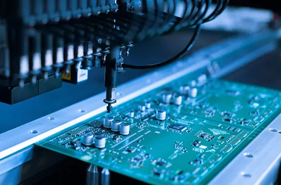
PCB connectors are widely used in PCB manufacturing and assembly to support modular and scalable circuit designs.
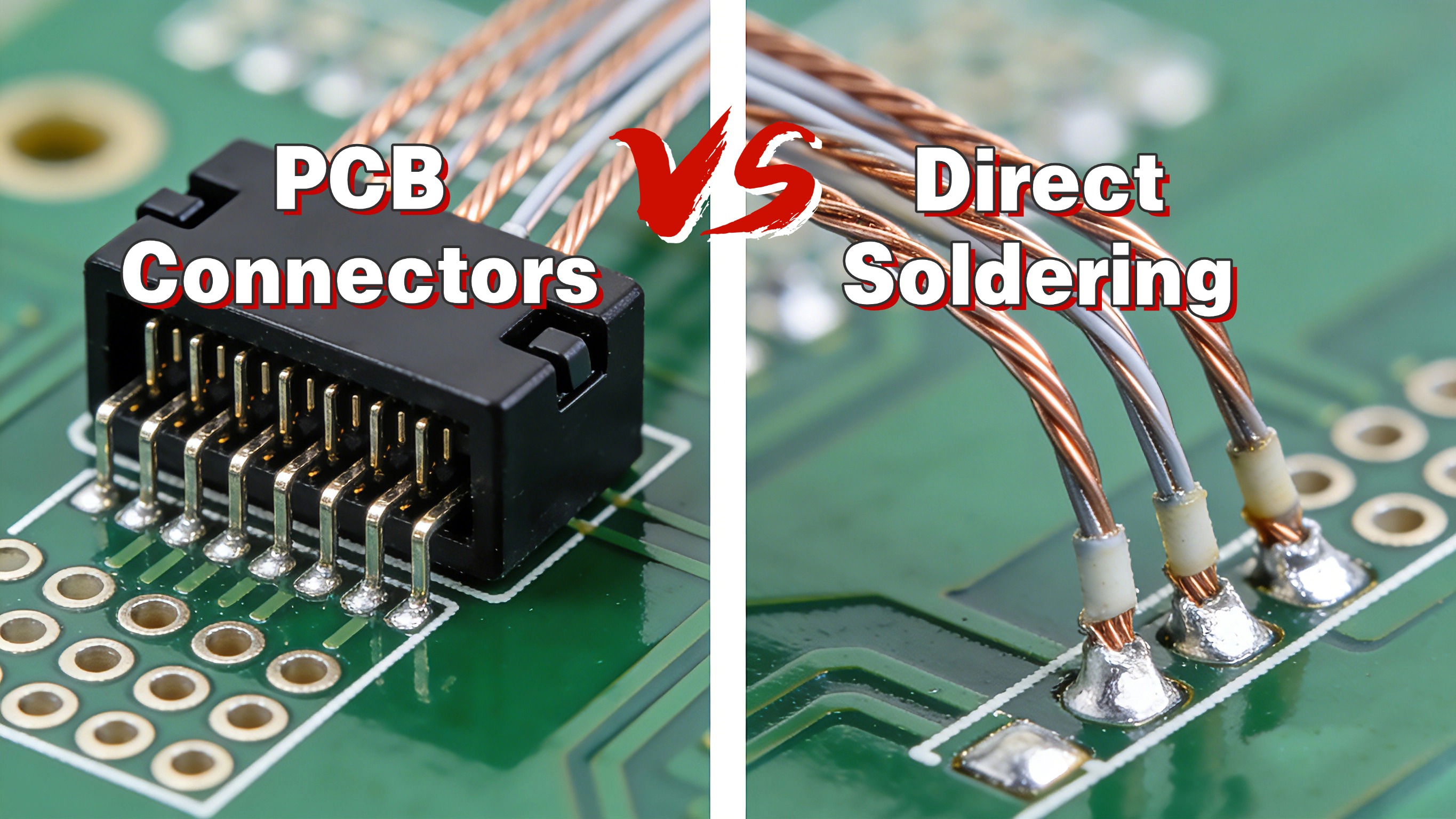
PCB Connectors vs Direct Soldering
Compared with direct soldering, PCB connectors offer greater flexibility. While soldered joints are permanent, connectors allow easy disconnection, replacement, and upgrades.
 You may also find this guide helpful:
How to Solder a PCB Circuit Board Without Errors?
Core Roles of PCB Connectors in Complex Circuits
1. Ensuring Stable Electrical Connections
PCB connectors, through precision design and superior materials, provide durable and reliable electrical connections for complex circuits.
a) Reducing Contact Resistance:
- Utilizing gold/silver-plated copper alloy contacts to enhance conductivity
- Designing multi-point contact structures to increase effective contact area
- Maintaining reasonable contact pressure to reduce oxidation effects
- Controlling contact resistance to milliohm levels, improving energy efficiency and reducing heat generation
b) Minimizing Signal Loss:
- Using low-loss dielectric materials to reduce high-frequency attenuation
- Optimizing pin layout to shorten signal paths
- Designing appropriate terminations to reduce reflection loss
- Ensuring insertion loss meets requirements for GHz-level signal transmission
2. Supporting Modular and Scalable Design
Connectors are key to realizing the modular architecture of electronic devices.
a) Facilitating System Upgrades:
- Providing standardized physical interfaces to ensure module compatibility
- Supporting hot-swapping functionality to improve system availability
- Enabling plug-and-play functionality through foolproof design
- Extending product lifecycle and reducing upgrade costs
b) Simplifying Design and Testing:
- Supporting parallel module development, shortening development cycles
- Each module can be independently verified and tested, reducing complexity
- Clearly defining interface specifications to simplify system integration
- Effectively managing technical risks and improving development efficiency
3. Simplifying PCB Assembly and Maintenance
Connectors optimize production processes and reduce maintenance difficulties.
a) Improving PCBA Efficiency:
- Supporting automated assembly, compatible with SMT/through-hole machines
- Enabling parallel module production followed by final assembly
- Reducing soldering density and improving production yield
- Increasing overall production efficiency by over 30%
b) Reducing Repair Costs:
- Supporting rapid fault localization and module replacement
- Enabling board-level repair without requiring chip-level operations
- Reducing the need for specialized repair equipment
- Shortening average repair time by 50-80%
4. Supporting High-Speed and High-Frequency Signal Transmission
Modern connectors meet the stringent signal quality requirements of high-speed circuits.
a) Ensuring signal integrity:
- Strict control of impedance continuity (50Ω/100Ω differential)
- Optimized grounding layout, crosstalk below -40dB
- Precise matching of differential pair lengths
- Ensuring clear waveforms and accurate timing for high-speed signals
b) Reducing EMI interference:
- Metal casing provides complete shielding
- Optional integrated filtering components to suppress noise
- Balanced design reduces common-mode current
- Helps the system pass FCC/CE and other EMC certifications
Types of PCB Connectors Used in Complex Circuits
1.Board-to-Board Connectors:
Used to connect multiple PCBs within a system
Ideal for compact and stacked designs
Wire-to-Board Connectors:
2.Common in power and signal input
Widely used in industrial and consumer electronics
3.High-Speed and RF Connectors:
Designed for high-frequency and high-data-rate applications
Essential in communication and networking equipment
4.Power Connectors:
Support high current and voltage
Critical for system safety and reliability
Why PCB Connectors Are Critical in Complex Circuit Design
Without proper connectors, complex circuits may suffer from signal interference, thermal issues, and frequent failures. A well-designed connector system improves overall reliability and ensures smooth PCB assembly and long-term operation.
Key Factors to Consider When Choosing PCB Connectors
Electrical Performance Requirements
Mechanical and Environmental Considerations
PCB Layout and Space Constraints
Applications of PCB Connectors in Complex Electronic Systems
These industries rely heavily on reliable PCB manufacturing and PCBA solutions.
Common Problems Caused by Poor PCB Connector Design
How HongRong (Shenzhen) Electronics Co., Ltd. Supports Reliable PCB Connector Integration
HongRong (Shenzhen) Electronics Co., Ltd. provides one-stop PCB manufacturing and PCB assembly services with over 20 years of industry experience. From connector selection during design to precision PCBA and quality testing, HongRong helps customers optimize connector performance in complex circuit applications.
Conclusion: The Essential Role of PCB Connectors in Complex Circuits
PCB connectors are indispensable components in complex circuits. They directly impact system performance, reliability, and manufacturability. Choosing the right connectors—and the right PCB assembly partner—ensures long-term success in modern electronic products.
FAQ: PCB Connectors & PCB Assembly
Q1: Why are PCB connectors important in PCB assembly?
PCB connectors improve assembly efficiency, reduce soldering defects, and allow modular design and easy maintenance.
Q2: Are PCB connectors better than soldering?
Each has its use. Connectors offer flexibility and serviceability, while soldering provides permanent connections when needed.
Q3: How do PCB connectors affect signal integrity?
High-quality connectors maintain impedance control and reduce signal loss, which is critical in high-speed and RF circuits.
Q4: Can PCB connectors reduce PCBA failures?
Yes. Proper connector selection and assembly significantly reduce contact issues, thermal problems, and long-term failures.


 PCB AssemblyHRPCBA is a PCBA China manufacturer offering high-quality PCB assembly services with full-process support, from design to assembly and testing.
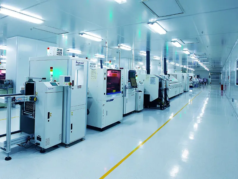 PCB ManufacturingHRPCBA is a leading PCB board manufacturer offering precision PCB fabrication services. Get high-quality boards with fast turnaround and competitive pricing
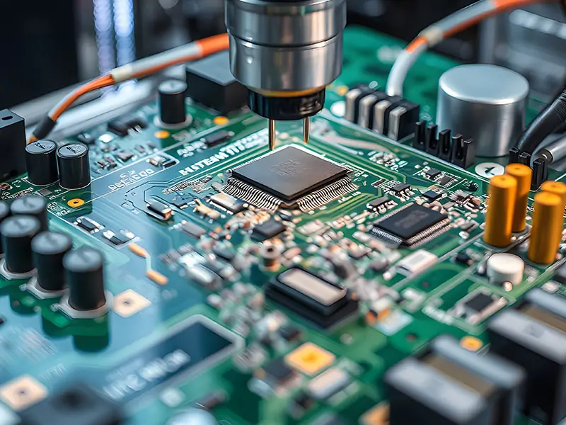 CapabilitiesDiscover HRPCBA’s robust PCB capabilities in custom PCB manufacturing services, where we transform your ideas into high-quality, functional circuit boards.