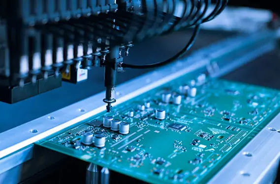
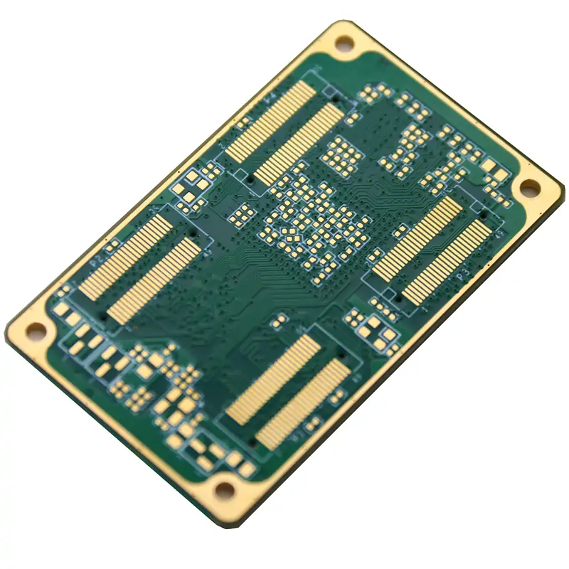
A printed circuit board (PCB) is an essential part of almost every electronic product. It connects electronic components and provides the paths through which electrical signals travel. From household electronics to industrial equipment, PCB quality plays an important role in the performance and reliability of the final product.
However, a board that looks fine on the outside may not work properly. Broken traces, unwanted connections, soldering problems, or incorrectly installed components can all cause circuit failures. For manufacturers, engineers, and purchasing professionals, understanding how to test a PCB before it moves to the next production stage is important.
So, how do you test a PCB board? Do you need complicated equipment? In many cases, basic checks can start with a few common tools. This guide walks through a practical PCB testing process, explains what to look for, and covers some common problems you may encounter.
1. What Tools Do You Need to Test a PCB?
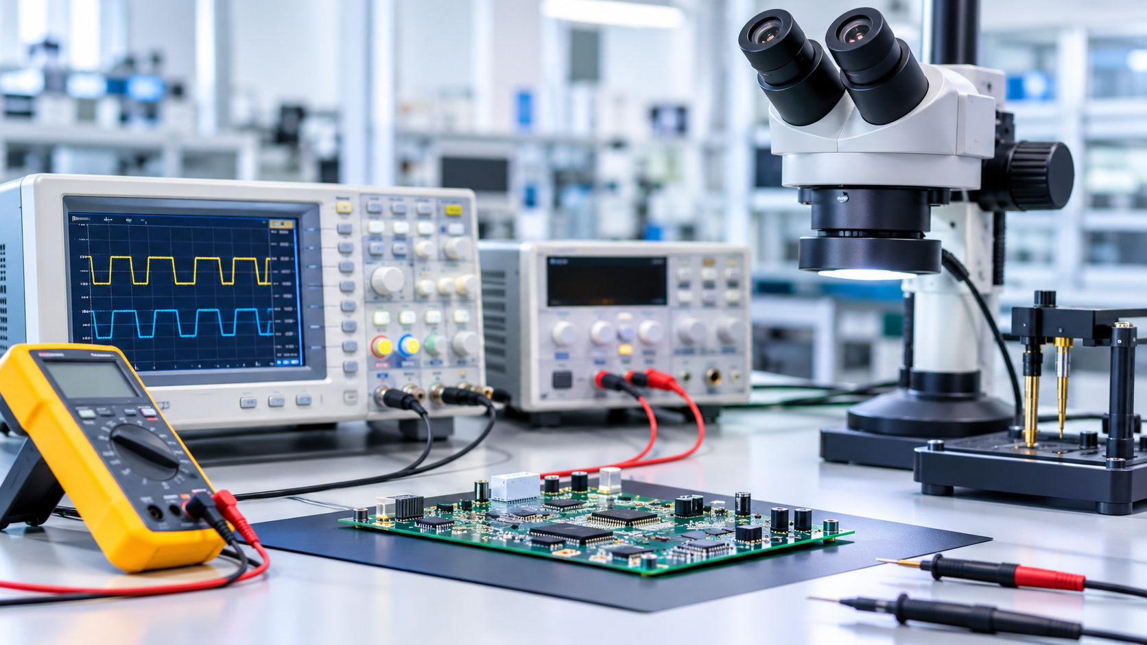
Before starting, prepare the right tools for the job. Basic PCB testing does not always require a large collection of specialized equipment. Some common tools include:
-
Multimeter: Used to measure resistance and voltage and check whether electrical connections are present. It is one of the most useful tools for basic PCB testing.
-
Bench Power Supply: Provides controlled power to the board. Voltage and current limits can be adjusted, which is especially helpful during the first power-up.
-
Magnifying Glass or Microscope: Helps inspect small solder joints, damaged pads, scratches, solder bridges, and other details that may be difficult to see with the naked eye.
-
Oscilloscope: Used to observe changing electrical signals, such as clock signals, pulses, and communication waveforms. It is useful when more detailed circuit checks are needed.
For simple checks, a multimeter may be enough. However, if you need to confirm that a circuit operates correctly, additional tools may be required.
2. How to Test a PCB Board Step by Step?

PCB testing is easier to manage when it follows a clear order. Start with visual and basic electrical checks before applying power. This helps reduce the chance of overlooking a problem or damaging the board during testing.
Step 1: Inspect the PCB
Start by looking closely at the board's surface and checking for visible damage.
Look for scratches, cracks, damaged copper traces, lifted pads, or other unusual marks. If you are testing an assembled PCBA, also check for missing components, incorrect component orientation, poor solder joints, or solder bridges.
This step may seem simple, but it can reveal problems caused during manufacturing, transportation, or assembly. For purchasing professionals, visual inspection is also a practical first step when assessing product quality.
Step 2: Check Electrical Connections
After the visual inspection, use a multimeter's continuity mode to check whether selected connections are present.
Place the probes on two points that should be connected and observe the meter. If a connection that should be present is not detected, there may be a broken trace, a poor contact, or another connection problem.
However, a continuity beep does not automatically mean the circuit is fully correct. Some connections have specific resistance requirements, so readings should be checked against the circuit design when necessary.
Step 3: Look for Short Circuits
A short circuit occurs when electrical connections are made between points that should not be connected. For example, a short may occur between a power line and ground, or between nearby pads where excess solder has created an unwanted connection.
Before powering the board, use a multimeter to check relevant circuits for unexpected connections.
Keep in mind that some circuits naturally have low resistance, and capacitors may affect readings during measurement. A single low resistance reading does not always mean the board is shorted. The circuit design, measurement points, and changes in the reading should all be considered.
Step 4: Check Components and Their Connections
If you are testing an assembled PCB, check whether the components are installed correctly.
Confirm that component models match the BOM, positions are correct, polarized components face the right direction, and solder joints are properly formed. For example, a diode or electrolytic capacitor installed in the wrong direction may prevent the circuit from working and could damage the component.
If a component is suspected to be faulty, further measurements may be needed based on its specifications and the circuit schematic. Visual appearance alone cannot confirm that every component is electrically sound.
Step 5: Power Up the PCB
Once the basic checks are complete, move on to the power test.
Use an adjustable power supply and set the voltage and current limits according to the circuit requirements. After applying power, monitor the current draw and check whether the voltage at key points matches the expected values.
If you notice excessive current, rapid heating, an unusual smell, or smoke, stop the test immediately and investigate the cause. Do not continue powering the board in an attempt to make it work.
This step helps confirm that the PCB can operate under the required power conditions, rather than simply looking acceptable.
Step 6: Check Whether the Circuit Works
A PCB that powers up is not necessarily functioning correctly. You still need to check whether it performs the tasks it was designed to do.
For example, a power board should provide the expected output voltage. A communication board should be able to send or receive signals correctly. A control board should respond to its inputs and produce the required outputs.
For complex or fast-changing signals, an oscilloscope or other test equipment may be needed. The checks should be based on the product's design requirements, rather than simply confirming that an indicator light turns on.
Step 7: Record the Test Results
After testing, record the results, including the test items, measured values, problems found, and any retest results after repair or adjustment.
These records are useful for production, quality tracking, and troubleshooting. For purchasing professionals, clear test records can also help determine whether a supplier follows a defined inspection process instead of relying only on a quick visual check before shipment.
3. Common PCB Testing Methods Used in Manufacturing
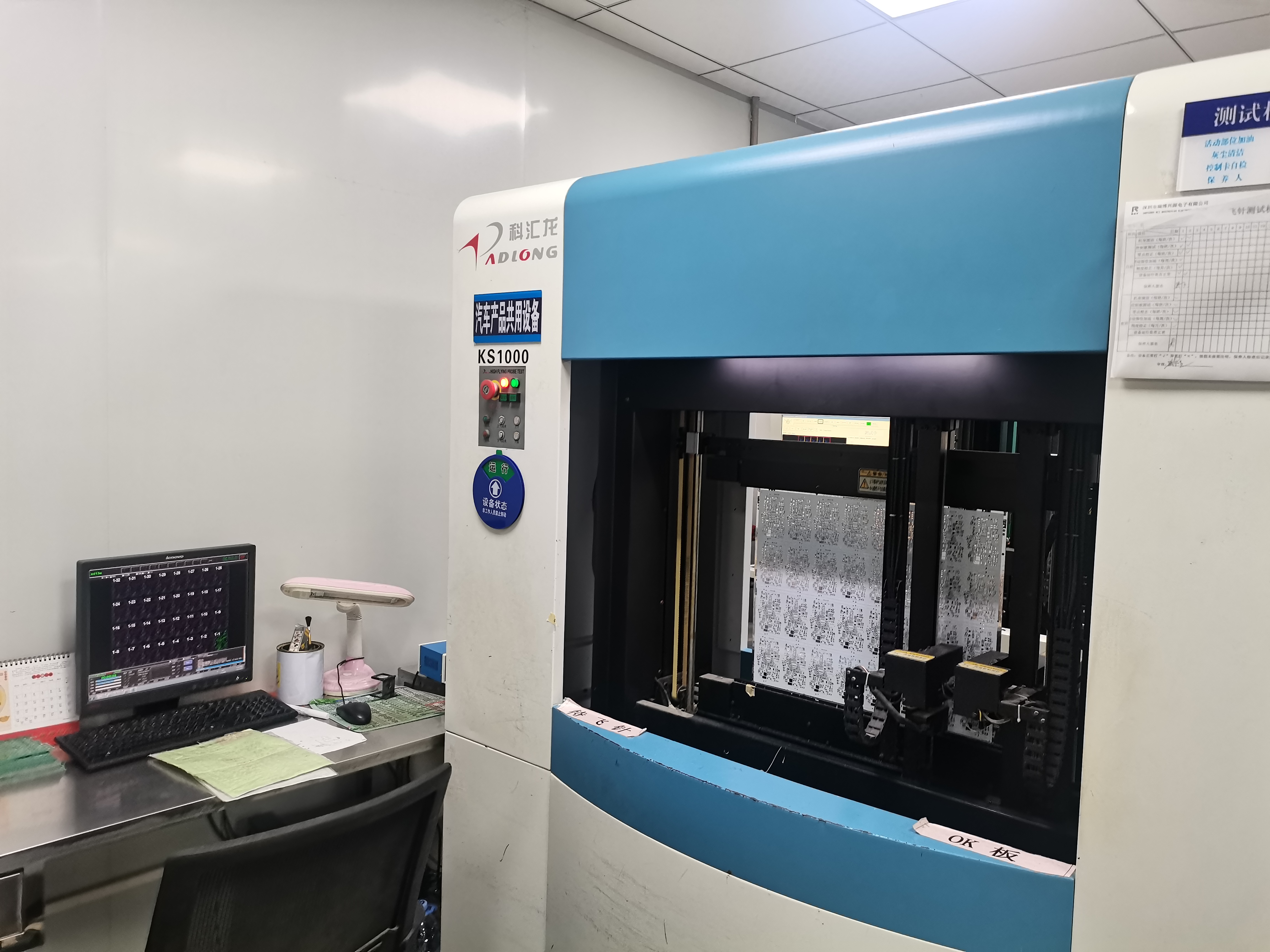
During PCB manufacturing and PCBA assembly, different testing methods may be used. The choice depends on the board's design, production volume, complexity, and customer requirements.
| Testing Method |
What It Checks |
| Visual Inspection |
Checks the board surface, traces, soldering, and visible defects |
| Continuity Test |
Confirms whether selected electrical paths are connected |
| Electrical Test |
Checks for problems such as open circuits or short circuits |
| AOI (Automated Optical Inspection) |
Uses images to inspect visible circuit or assembly defects |
| X-ray Inspection |
Examines hidden solder joints and certain internal connections |
| Functional Test |
Checks whether the assembled circuit operates as intended |
Each method serves a different purpose. AOI mainly checks visible features, while X-ray inspection can help examine solder joints that cannot be seen directly, such as some BGA connections. Functional testing focuses on how the assembled circuit performs during operation.
Not every PCB requires every test. The testing plan should match the board's requirements. For example, electrical testing of a bare PCB focuses on its connections, while an assembled PCBA may also need component and functional checks.
For more information, see PCB Assembly Testing, which introduces common testing methods used for assembled circuit boards.
4. Common Problems Found During PCB Testing
Different test results may point to different problems. Knowing what they may indicate can help you decide what to check next.
| Problem Found |
Possible Cause |
| No continuity |
Broken trace, poor connection, or faulty solder joint |
| Unexpected connection |
Short circuit, solder bridge, or unwanted contact |
| Voltage is incorrect |
Power supply issue, component fault, or abnormal circuit load |
| Current is too high |
Possible short circuit, damaged component, or circuit problem |
| Component does not work |
Damaged component, incorrect installation, or connection issue |
| Product function fails |
Circuit, connection, component, or software-related problem |
These symptoms do not always have a single cause. For example, an incorrect output voltage may come from the power supply or from a load connected to the circuit. Troubleshooting should therefore be based on the schematic, measurements, and actual circuit behavior.
Contamination can also affect circuit performance in some situations. Dust, residue, or other unwanted material may cause problems, especially when it affects sensitive areas of the board. If cleaning is necessary, read How to Clean a PCB Without Damaging Components? for practical precautions.
5. How to Make PCB Testing More Reliable?
Testing depends not only on the equipment but also on how the checks are performed. A few practical habits can help reduce mistakes and improve efficiency.
Check against the design. Do not rely only on experience or assumptions. The schematic, BOM, and test requirements help confirm what should be connected and what values are expected.
Use the right tools. A multimeter may be suitable for basic connection checks, while signal or functional problems may require an oscilloscope or dedicated test equipment.
Follow the correct order. Whenever possible, complete visual and unpowered checks before applying power. This helps reduce the risk of unnecessary damage.
Do not rely on a single test. A board that passes visual inspection may still have electrical problems. Likewise, passing a power test does not confirm that every function works correctly.
Keep test records. Recording measurements and problems helps identify repeated failures and makes troubleshooting easier, especially during prototype verification and production.
For PCB designers, adding suitable test points during the design stage can also make later inspection and troubleshooting easier. Testing should not be considered only after manufacturing; it is closely connected to design and production planning.
6. FAQs About PCB Testing
Q1: Can I test a PCB with only a multimeter?
Yes. A multimeter can perform basic checks, including continuity, resistance, and voltage measurements. However, it cannot cover every testing requirement, especially complex signals and full functional verification.
Q2: Should I test a PCB before powering it on?
Yes. Checking the board's appearance, electrical connections, and possible short circuits before applying power can help reduce the risk of damage.
Q3: How do I know if my PCB is working properly?
The PCB should meet its design requirements, including correct connections, expected voltage levels, and proper circuit operation. The specific tests depend on the board's intended use.
Q4: Is PCB testing the same as PCBA testing?
No, not exactly. Bare PCB testing mainly checks the board, electrical connections, and related characteristics. PCBA testing also covers component installation, soldering quality, and circuit functionality.
Conclusion
Testing a PCB does not have to be complicated, but it should follow a sensible order. Start with a visual inspection, check connections and possible shorts, inspect components, verify the power supply, and then test the circuit's functions.
For engineers, manufacturers, and purchasing professionals, understanding this process helps identify problems earlier, reduce rework, and make more informed quality decisions.
A testing plan that matches the board's actual requirements is often more valuable than simply adding more test steps.



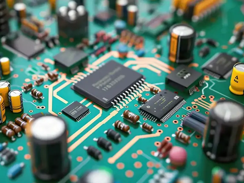 PCB AssemblyHRPCBA is a PCBA China manufacturer offering high-quality PCB assembly services with full-process support, from design to assembly and testing.
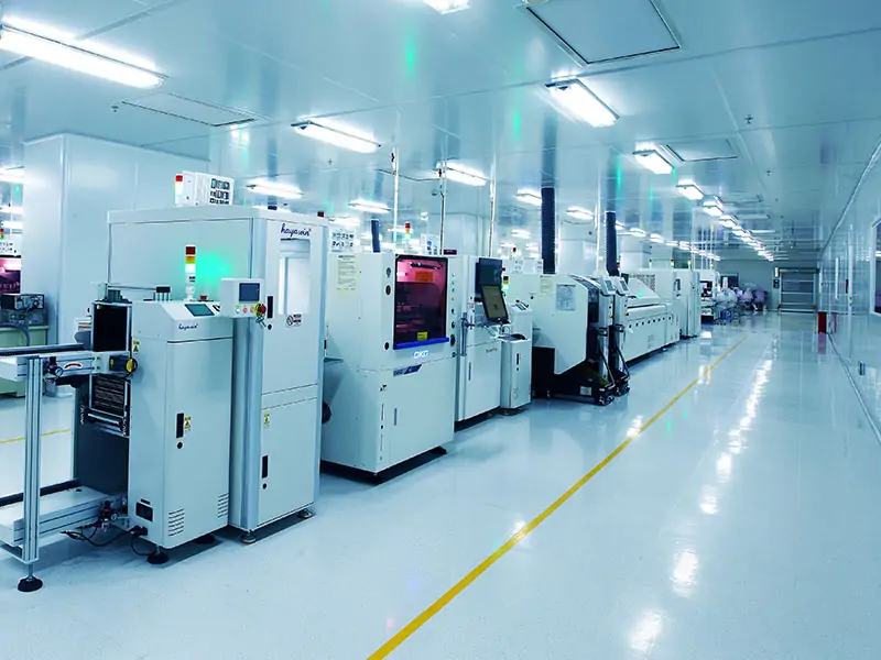 PCB ManufacturingHRPCBA is a leading PCB board manufacturer offering precision PCB fabrication services. Get high-quality boards with fast turnaround and competitive pricing
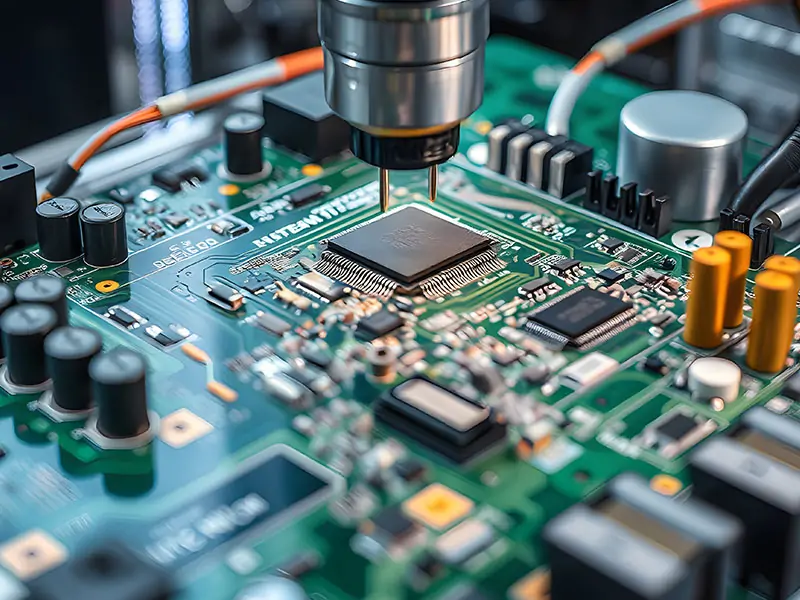 CapabilitiesDiscover HRPCBA’s robust PCB capabilities in custom PCB manufacturing services, where we transform your ideas into high-quality, functional circuit boards.