What Engineers Often Overlook About High-Voltage PCB Design
A customer once sent us a failed control board from a home appliance project. The power section had already passed functional testing, EMC verification, and even short-term aging tests. Yet after several months in the field, some units began showing carbonization marks near the AC input area. In a few cases, the low-voltage control side unexpectedly carried high voltage.
The first reaction from many engineers is usually:
“Was the PCB material defective?”
In reality, the issue is rarely caused by a single factor. AC safety on a PCB is not determined by board thickness alone, nor by adding a few extra millimeters of spacing. Long-term reliability depends on how layout, materials, contamination control, manufacturing quality, and environmental conditions interact over time.
The short answer is yes — AC can absolutely be used safely on a PCB.
But only when the design follows proper engineering practices from the beginning.
Why AC Voltage Is More Challenging Than Many Designers Expect
Compared with low-voltage DC systems, AC mains introduces several risks that are easy to underestimate during layout.
The first is peak voltage. A 220V AC system does not actually operate at 220V continuously. Its peak voltage reaches approximately 311V. For 110V systems, the peak is around 155V.
This matters because insulation failure and arcing behavior are determined by peak electric field stress, not just RMS voltage.
The second challenge is contamination. Many engineers calculate spacing based on ideal laboratory conditions, but real products rarely operate in clean environments forever. Dust, moisture, flux residue, and airborne contaminants gradually accumulate on the PCB surface.
Over time, these contaminants create conductive leakage paths along the board surface.
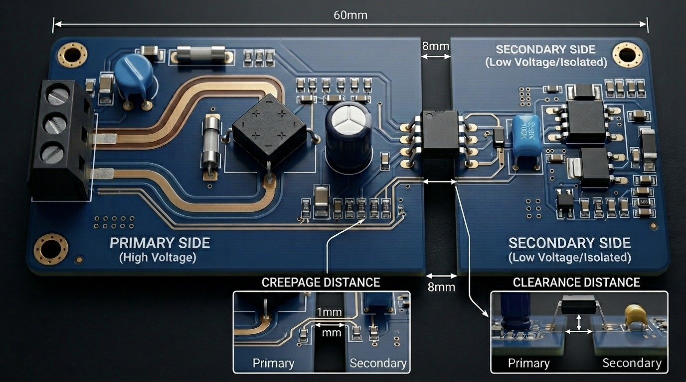
This is why creepage distance is often more critical than clearance distance.
In theory, two conductors separated by air may appear safe. In practice, leakage along a contaminated PCB surface usually becomes the first failure mechanism long before air breakdown occurs.
One common misunderstanding among newer designers is assuming that passing a short Hi-Pot test automatically guarantees long-term safety.
Unfortunately, that is not always true.
Many insulation failures only appear after months of humidity exposure, thermal cycling, or vibration stress.
The Real Engineering Priority: Creepage vs. Clearance
When engineers first learn high-voltage PCB design, they often focus heavily on clearance spacing because it is easy to visualize. However, in actual field failures, creepage issues are frequently the bigger problem.
For a typical 220V AC product, the electrical clearance may only require around 2.5mm to 3.0mm, while creepage distance often needs to exceed 6mm.
That difference surprises many designers.
The reason is simple: surface contamination dramatically lowers insulation reliability over time.
Even a board that looks clean after assembly may slowly develop conductive residue in humid environments such as kitchens, industrial workshops, or outdoor installations.
From manufacturing experience, products installed near motors, compressors, or switching power devices usually require more conservative creepage design than laboratory calculations suggest.
This is especially true for long-lifetime products expected to operate continuously for five to ten years.
Material Selection Matters More Than Many Buyers Realize
Not all FR4 materials behave the same way under high voltage.
In lower-cost projects, some buyers focus almost entirely on PCB price while overlooking insulation reliability.
However, for AC applications, the Comparative Tracking Index (CTI) of the material has a major impact on long-term safety.
Higher CTI materials provide better resistance against surface tracking caused by contamination and humidity.
In practical engineering, FR4 materials with:
are generally preferred for AC power designs.
Interestingly, some failures are not caused by insufficient spacing at all. Instead, the issue comes from inconsistent laminate quality, moisture absorption, or poor process control during fabrication.
This is why experienced engineers usually evaluate the PCB supplier’s manufacturing consistency as carefully as the layout itself.
Slotting Helps — But It Is Not a Shortcut
Slotting is commonly used to improve creepage distance when board space is limited.
It is effective, but many designers misunderstand what it actually does.
A slot only extends the surface leakage path. It does not improve the straight-line air clearance between conductors.
Some junior engineers assume that adding a slot automatically solves all isolation concerns.
In practice, if the air gap itself is still insufficient, arcing can still occur even with aggressive slotting.
Manufacturing details also matter more than expected.
Sharp slot corners may become stress concentration points during thermal cycling or vibration. Over time, small cracks can develop around these areas, especially in industrial environments.
For this reason, routed slots with rounded corners are usually preferred over narrow or aggressively shaped cuts.
Conservative mechanical design often improves reliability more than aggressively shrinking PCB size.
One Common Failure Mechanism: Flux Residue
One of the most underestimated risks in AC PCB assembly is flux contamination.
A board may pass electrical testing immediately after production yet still fail months later because ionic residue slowly creates conductive paths across the isolation area.
We have seen cases where the original layout spacing was technically correct, but incomplete post-assembly cleaning reduced insulation performance dramatically in humid conditions.
This is particularly common in products exposed to kitchen steam, industrial dust, or outdoor condensation.
Because of this, cleaning quality can become just as important as layout spacing itself.
Many engineers focus heavily on PCB design rules while overlooking the assembly process.
In reality, manufacturing quality and cleanliness are often part of the insulation system itself.
For higher-reliability AC products, ionic contamination control and conformal coating are frequently worth the additional manufacturing cost.
AC Layout Design Is Always a Trade-Off
High-voltage PCB design is rarely about finding one “perfect” spacing value.
Real projects involve constant trade-offs between:
For example, increasing spacing improves safety but also enlarges board size. Adding slots improves creepage but may weaken mechanical rigidity. Thick copper improves current handling but can complicate soldering consistency and thermal balance.
Experienced engineers rarely optimize only one parameter.
Instead, they look for a balance that remains reliable across mass production, environmental stress, and long-term field operation.
That mindset is what separates theoretical compliance from real-world reliability.
Different Products Require Different Safety Strategies
Not every AC PCB faces the same environmental stress.
A household appliance controller installed inside a clean indoor appliance has very different requirements compared with an industrial motor driver operating near vibration and oil contamination.
In consumer electronics, standard 1.6mm FR4 with proper spacing is often sufficient.
In industrial power systems, engineers may choose:
-
Larger creepage margins
-
Thicker PCB structures
-
Reinforced insulation
-
Conformal coating
Motor control boards create another challenge entirely. High current switching generates EMI that can interfere with nearby sensor traces if spacing and routing are not carefully controlled.
Interestingly, some of the most difficult AC PCB problems are not caused by voltage itself, but by the interaction between:
-
High voltage
-
Noise
-
Humidity
-
Manufacturing tolerances
Before Releasing an AC PCB to Production
Before mass production, experienced engineers usually recheck several practical questions rather than only verifying schematic correctness.
For example:
-
Will the spacing remain safe after humidity or contamination?
-
Can the PCB manufacturer process the slots consistently?
-
Will assembly operators accidentally bridge isolation areas?
-
Can the design survive long-term thermal aging?
-
Is the selected material suitable for the actual environment?
These questions often reveal risks that are invisible during the initial layout review.
Frequently Asked Questions
1. Can a standard 1.6mm PCB safely carry 220V AC?
Yes. In fact, 1.6mm FR4 remains one of the most common choices for AC power boards.
However, thickness alone does not determine safety. Proper creepage, clearance, material quality, and manufacturing control matter far more.
2. Can solder mask be used as extra insulation?
Technically, some standards allow solder mask to contribute to insulation performance under controlled conditions.
However, most experienced engineers avoid relying on solder mask alone because it can be scratched, contaminated, or degraded over time.
Physical spacing is still considered the safest long-term approach.
3. Does slotting completely solve creepage problems?
No.
Slotting only increases the surface leakage path. It does not replace clearance requirements through air.
This distinction is extremely important and often misunderstood in early high-voltage PCB designs.
4. Is conformal coating always necessary?
Not always.
For clean indoor products, proper spacing and cleaning may already be sufficient.
However, in humid, dusty, or industrial environments, conformal coating can significantly improve long-term insulation reliability.
Final Thoughts
Safe AC PCB design is not achieved by following a single spacing rule or copying a reference layout.
Long-term reliability comes from understanding how electrical stress, contamination, materials, manufacturing quality, and environmental conditions interact together over time.
Some boards pass every initial test yet still fail months later because small manufacturing or layout compromises gradually weaken insulation performance in real operating conditions.
That is why experienced engineers often design more conservatively than the minimum standard requires.
Over the years, we have learned that reliable AC PCB manufacturing depends just as much on fabrication consistency, cleaning quality, and process control as it does on the original layout itself.
From PCB fabrication and slot routing to SMT assembly, cleaning, and Hi-Pot testing, every stage affects final product safety.
For products involving AC mains, investing more effort during the design and manufacturing stage is usually far less expensive than dealing with field failures later.




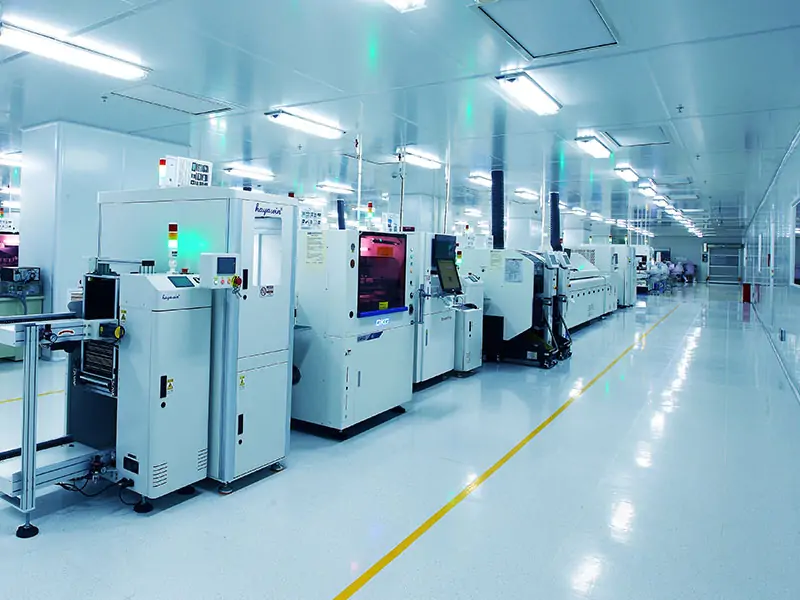
 PCB AssemblyHRPCBA is a PCBA China manufacturer offering high-quality PCB assembly services with full-process support, from design to assembly and testing.
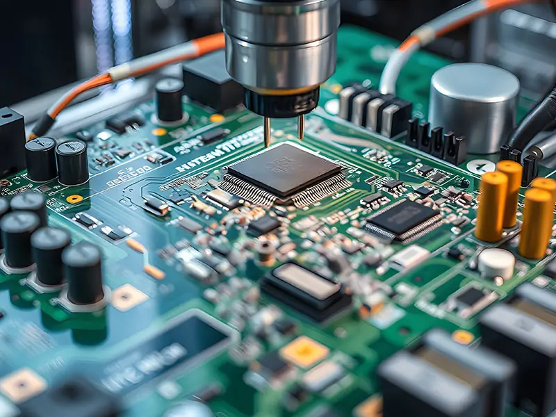
 PCB ManufacturingHRPCBA is a leading PCB board manufacturer offering precision PCB fabrication services. Get high-quality boards with fast turnaround and competitive pricing
 CapabilitiesDiscover HRPCBA’s robust PCB capabilities in custom PCB manufacturing services, where we transform your ideas into high-quality, functional circuit boards.