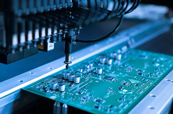
A printed circuit board (PCB) can look perfectly normal and still have a problem. A broken copper connection, an unexpected short circuit, or a poorly soldered component may prevent an electronic device from working correctly. Some faults are easy to spot, while others only appear when the board is powered on or operates under a specific load.
This is why PCB testing is an essential part of electronics manufacturing. It helps identify manufacturing defects, verify electrical connections, and determine whether an assembled circuit board performs according to its design requirements.
For businesses purchasing electronic components or developing new products, understanding PCB testing also makes it easier to evaluate a manufacturing supplier. Different tests detect different types of problems, and no single method can guarantee that every possible fault has been eliminated.
In this guide, we will explain the main PCB testing methods, how to identify common faults, and what to consider when choosing a PCB and PCBA manufacturer.
1. Why Does a PCB Need to Be Tested?
PCB testing serves two closely related purposes: detecting faults and verifying performance.
Fault detection focuses on identifying problems such as open circuits, short circuits, damaged components, and soldering defects. Performance testing checks whether the circuit board can perform its intended functions under specified operating conditions.
Before choosing a testing method, it is important to understand the difference between PCB and PCBA.
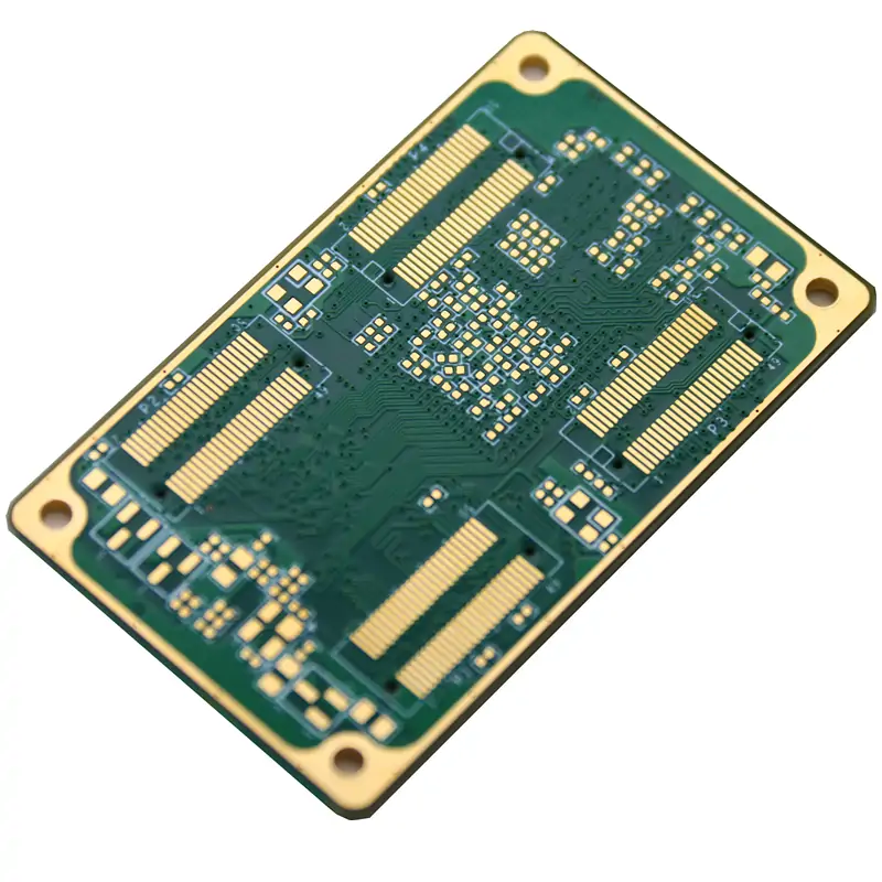
A bare PCB provides the physical structure and conductive paths that connect different parts of a circuit. A PCBA, or printed circuit board assembly, is a PCB with electronic components installed, including integrated circuits, resistors, capacitors, and connectors.
The two require different types of testing. A bare PCB is commonly checked for electrical connection problems, such as open circuits and short circuits. After components are installed, additional inspections and tests may be needed to verify soldering quality, component placement, electrical behavior, and overall functionality.
Consider a simple example. A newly manufactured PCB may have no visible scratches or other damage, but one of its copper connections may be incomplete. Once the board is assembled, the affected circuit may fail to operate. Visual inspection alone would not necessarily identify the problem.
Testing at the appropriate production stages helps detect such issues before the product reaches the customer. It can also reduce unnecessary troubleshooting, rework, and delays during production.
2. What Problems Can PCB Testing Detect?
The problems found during PCB testing depend on the board design, manufacturing process, and components used. However, several fault types occur across a wide range of electronic products.
| Common fault |
What it means |
Possible impact |
| Open circuit |
An intended electrical connection is broken or incomplete |
Signals or power may not reach the required point |
| Short circuit |
Two points that should remain electrically separate become unintentionally connected |
Abnormal current or circuit malfunction |
| Soldering defect |
A solder joint does not provide the required electrical or mechanical connection |
Intermittent operation or component failure |
| Component problem |
A component is missing, incorrectly installed, damaged, or outside its required specification |
Incorrect circuit behavior |
| Functional failure |
The assembled board cannot perform a required task |
The finished product may not work as intended |
These problems do not always have an obvious cause. For example, if a PCBA fails to start, the issue could come from its power supply, a short circuit, a damaged component, or a problem in the control circuit.
The correct approach is to use the observed symptoms as a starting point and then perform suitable tests to locate the cause.
This is also why testing should not be treated as a single final inspection. Electrical checks can identify certain connection problems, while functional testing can reveal failures that only become apparent when the board operates.
3. What Are the Main Methods for Testing a PCB?
Different testing methods serve different purposes. Manufacturers select them according to the board design, production volume, component package, and quality requirements.
Visual Inspection
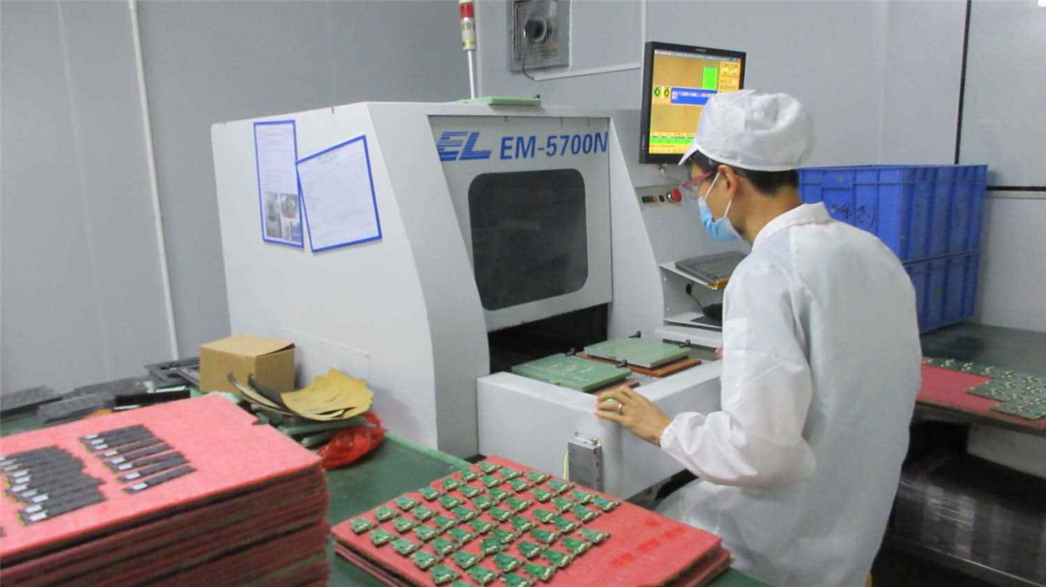
Visual inspection is usually one of the first checks performed on a PCB or PCBA. It can identify visible damage, missing components, incorrect component orientation, solder bridges, and other apparent assembly problems.
Automated Optical Inspection (AOI) uses cameras and image-processing software to examine the board against defined inspection criteria. It is useful for identifying many visible defects, particularly during high-volume assembly.
However, visual inspection cannot confirm every electrical connection or reveal every hidden solder joint problem. A board that looks correct may still require electrical or functional testing.
Continuity and Resistance Testing
A multimeter can help check whether selected points have the expected electrical connection. Continuity testing is useful for investigating possible broken connections, while resistance measurements can help identify unusual readings.
These tests are relatively straightforward, but the results must be interpreted in the context of the circuit. Capacitors, semiconductor devices, and parallel electrical paths can affect resistance readings. A low resistance reading does not automatically mean that a short circuit exists.
For a practical example, read HRPCBA's guide on how to wire an input jack to a PCB. It explains how visual inspection, continuity checks, and functional testing can be used together to verify electrical connections.
Electrical Testing for Bare PCBs
Before components are installed, manufacturers can use flying probe testers or dedicated electrical test fixtures to examine the board's conductive connections.
These methods help identify manufacturing defects such as open circuits and unintended connections between electrical nets. Flying probe testing is particularly useful for many prototype and low-volume applications, while dedicated fixtures can support efficient testing in suitable production environments.
The appropriate method depends on the design, required test coverage, and production needs.
X-Ray Inspection
Some solder joints are hidden beneath components and cannot be inspected directly from above. X-ray inspection helps examine selected internal structures, including solder joints beneath certain BGA packages.
It can provide information that ordinary visual inspection cannot. However, X-ray inspection does not replace electrical testing or prove that the circuit performs all its intended functions.
Functional Testing
Functional testing checks whether an assembled board performs the tasks it was designed to perform. Depending on the product, the procedure may involve applying power, supplying input signals, checking outputs, or testing communication with another device.
For example, a control board may need to receive an input signal and produce a corresponding output. A functional test checks whether that expected response occurs under the specified conditions.
You can learn more about this process through HRPCBA's PCBA functional testing service.
The table below summarizes the main differences.
| Testing method |
Main purpose |
Typical application |
| Visual inspection / AOI |
Find visible damage and assembly defects |
PCB and PCBA inspection |
| Continuity / resistance testing |
Investigate electrical connections |
Fault diagnosis |
| Flying probe / fixture-based electrical testing |
Check bare-board electrical connections |
PCB fabrication |
| X-ray inspection |
Examine selected hidden structures and solder joints |
PCBA inspection |
| Functional testing |
Verify specified operating functions |
Assembled circuit boards |
A reliable testing plan may combine several of these methods. The goal is not to perform every available test on every board, but to choose the methods that provide meaningful coverage for the product's actual risks.
4. How to Check PCB Performance and Troubleshoot Failures
Passing an initial inspection does not necessarily mean that a circuit board will operate correctly under every condition. A board may work without a load but fail when its current demand increases. Another may power on normally but produce an incorrect output or lose communication intermittently.
Performance testing should therefore be based on the product's specifications and intended operating environment.
Power supply testing checks whether the input voltage and important output voltages fall within their specified limits. Current consumption can also help identify potential problems when it differs significantly from the expected value.
Signal and communication testing verifies whether the board receives, processes, and outputs the required signals. Depending on the application, this may include checking signal levels, timing, or communication interfaces.
Operating-condition testing evaluates performance under defined loads, temperatures, or other relevant conditions. These tests should reflect the actual requirements of the product rather than relying on universal limits that may not apply to every design.
For example, an industrial control board may power on successfully but fail to respond to an input signal. The problem could be related to the input connection, power supply, configuration, control logic, or output circuit. Checking the relevant signals and comparing measurements with the design specifications can help narrow down the possible causes.
When a board fails a test, a structured troubleshooting process is more effective than replacing components at random.
1. identify which test failed and record the conditions under which the problem occurred.
2. check the basic connections, component orientation, connectors, and visible soldering.
3.compare the measurements with the schematic and applicable specifications to locate abnormal results.
4. Once the likely cause has been identified, appropriate repairs can be made and the relevant tests repeated to verify the outcome.
Safety matters throughout this process. Before performing resistance or continuity measurements, the circuit should be isolated from power and stored energy discharged safely. These measurement modes should not be used on an energized circuit unless the instrument and procedure explicitly permit it.
5. How to Choose a Reliable PCB and PCBA Manufacturer
For customers sourcing circuit boards, testing capability is an important part of supplier evaluation. The key question is not simply whether a manufacturer owns testing equipment, but whether its quality-control process matches the requirements of the product.
Start by asking what tests are performed on bare PCBs and what additional checks are available after assembly. A capable supplier should be able to explain the purpose and limitations of its inspection methods rather than presenting all tests as interchangeable.
It is also worth asking how failed boards are handled. A well-defined process should include recording failures, investigating their causes, documenting corrective actions when appropriate, and verifying repairs through suitable retesting.
For projects with specific performance or reliability requirements, provide the manufacturer with the relevant Gerber files, Bill of Materials (BOM), drawings, functional requirements, and acceptance criteria as early as possible. These details help the supplier assess the project and determine an appropriate testing approach.
Design decisions also influence testability. Accessible test points, suitable component spacing, and consistent design documentation can make inspection and troubleshooting easier. Reviewing these details before production may help avoid unnecessary manufacturing difficulties.
To understand how testing fits into a broader manufacturing process, visit HRPCBA's PCB Manufacturing Quality Control and Quality Assurance page.
Conclusion
Testing a PCB for faults and performance involves more than checking whether the board looks intact or powers on. Visual inspection, electrical testing, and functional verification each provide different information about product quality.
For a bare PCB, testing focuses on the integrity of its electrical connections and manufactured structure. For a PCBA, additional checks may be needed to evaluate solder joints, component installation, power behavior, signals, and the functions required by the finished product.
The most suitable testing strategy depends on the design, application, and acceptance criteria. Clear specifications, appropriate test methods, and a documented process for handling failures help manufacturers identify problems and give customers a better basis for evaluating quality.
HongRong (Shenzhen) Electronics Co., Ltd. provides one-stop PCB manufacturing and PCBA assembly services. If you are developing a new electronic product or preparing for production, visit HRPCBA.com to discuss your project requirements and request a quotation.



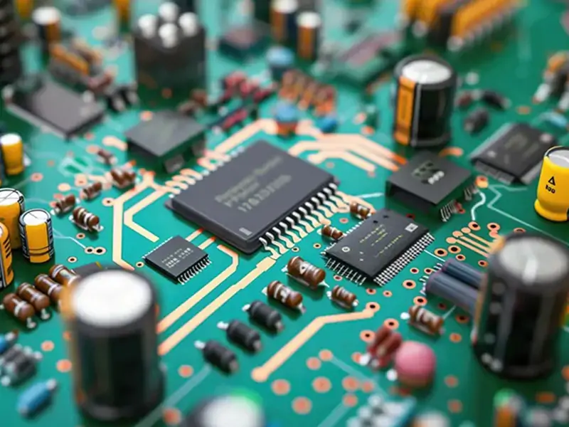 PCB AssemblyHRPCBA is a PCBA China manufacturer offering high-quality PCB assembly services with full-process support, from design to assembly and testing.
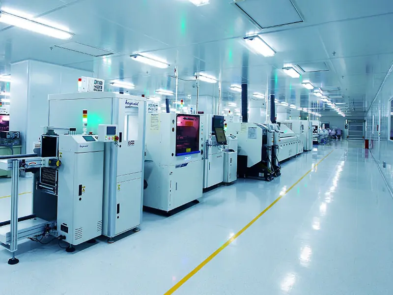 PCB ManufacturingHRPCBA is a leading PCB board manufacturer offering precision PCB fabrication services. Get high-quality boards with fast turnaround and competitive pricing
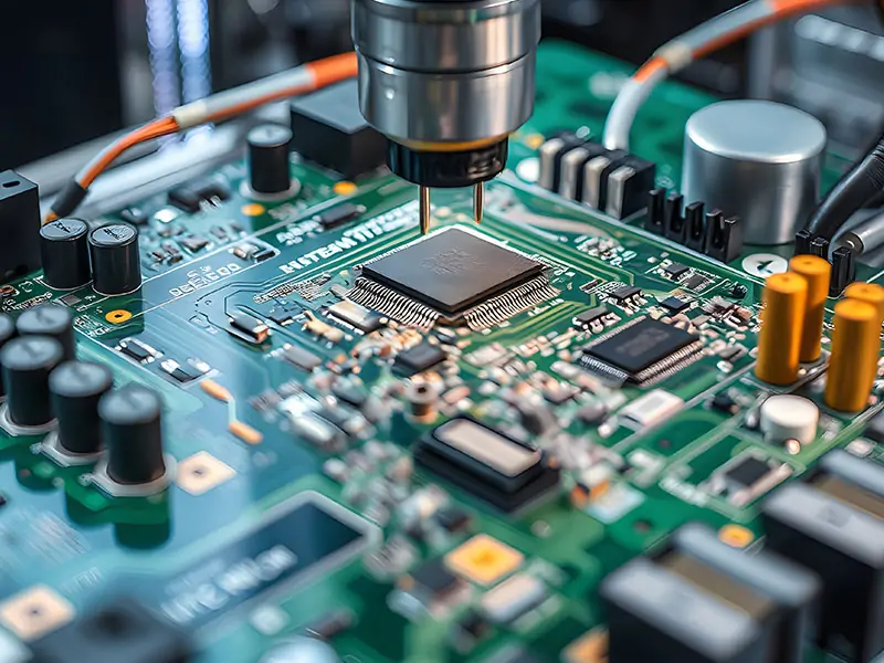 CapabilitiesDiscover HRPCBA’s robust PCB capabilities in custom PCB manufacturing services, where we transform your ideas into high-quality, functional circuit boards.